|
|
Post by Rebel on Sept 9, 2011 17:16:57 GMT -5
I had a question about this too, I'm wondeing though if the diagram you just posted is completely dc, the cdi looks like the cdi is ac with the two wires going to the small plug on it. DC cdi's have just one. Not that I'm an expert on these.
What I had been wondering was about the altered ac to dc circuit working because of the ac cdi.
Help us out on this noday.
|
|
noday
Non-Com
   "Sparky" Electronics Research and Development Officer
Posts: 90
|
Post by noday on Sept 9, 2011 18:26:26 GMT -5
homernukemmore or less YES, however that diagram has no lights included & the only thing powered from the "Main Power" circuit is the autochoke & the battery. scooters have both AC and DC lighting circuits, basically 2 different circuits. The AC circuit is run from the yellow wire between the stator and RR. Even though the yellow is an "IN" to the RR the RR still limits the AC voltage to 14.5 V. the DC output from the RR is on the RED and black wires. the green wire is grounded and is shared by both the AC and DC circuits. a distinction between ground and grounded is that grounded wires carry current flow to ground and often will have a measured voltage, when compared to ground ( or the (-) battery pole for 12V DC) part of the conversion is to connect the grounded end of green to the (-) battery pole rather than the frame. At the same time the starter uses only 1 wire, a switched red for + 12V to the starter. the crankcase is wired to the (-) battery pole, black. in pure 12V DC setup. all AC from the stator goes only to the RR. the RR 12 V DC output is fed to the battery, to keep the battery charged. one of the changes needed is to reconnect the auto choke so that it is powered by DC. if you try to use a half wave stator and RR for pure DC only, most times the RR will fail due to overload. most are rated for about 6 to 7 amps the RR is only designed to convert part of the stator output to DC @rebel the AC trigger pulse is from a single pole of the stator. there is no connection between the stator trigger pole circuit to the CDI and the AC that goes to the RR or to the DC side that goes to the battery. the DC conversion does not modify or change the CDI wiring. DC CDIs usually use 2 stator poles to power the CDI. this last diagram is somewhat confusing in that ground, itself, is used as a current conductor. ( this is almost always the case for a starter circuit, due to the large current flow involved ) aside from the starter circuit, the frame and motor case should not be used as part of electrical circuits, other than for grounding.
|
|
|
|
Post by homernukem on Sept 13, 2011 12:51:47 GMT -5
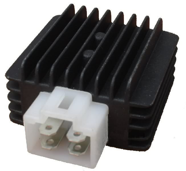
What I want to do is get a 4 post regulator/rectifier and basically go from there. It's one that looks like   I've taken off my choke and blocked the holes with quick steel. I'll just rewire the lights and what not to my liking. Probably throw a bunch of leds and whatever else. My scooter is completely apart right now, so I can get at the wiring as easy as I please. I guess I'll wire it up and let you know how long my ebay rectifier lasts running full DC |
|
|
|
Post by Rebel on Sept 13, 2011 13:55:13 GMT -5
What is the rectifier off of?
|
|
noday
Non-Com
   "Sparky" Electronics Research and Development Officer
Posts: 90
|
Post by noday on Sept 13, 2011 17:44:55 GMT -5
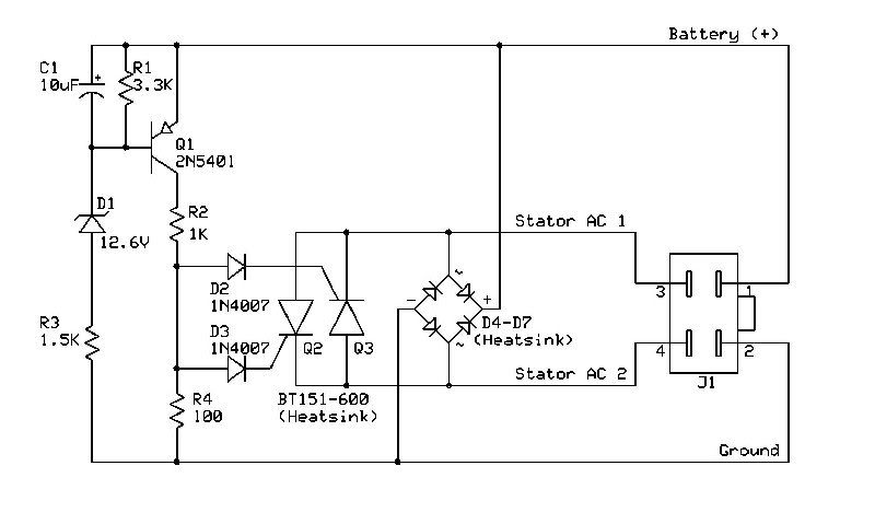
that is a generic half wave mixed AC DC RR.
notice it does not have a wire for the battery(-).
I expect you will be limited to about 6 amps (72 watts) of 12V DC.
you need 35 watts for the headlight so you will have 20 or so watts left for all the other lights.
you need an amp or 2 over the light power usage to charge the battery after cranking.
this is not really a conversion, you are just switching lights to the DC side
|
|
|
|
Post by zoomer on Sept 25, 2011 7:36:08 GMT -5
I'm trying to go all DC on my Bashan 150cc so I can tie everything into one supply panel to run my 10 amp oil cooler pump, the cooling fan, my instrument cluster, and enough lights to keep the cops off of my ass. FYI, do NOT run a universal R/R with the yellow and white hooked up unmodified to the yellows on the R/R. There was no magic black smoke as Noday predicted but if it hadn't been a sealed unit there probably would have.
So now I'm going to try to do it the right way, I ordered the Trail Tech R/R. I talked to the tech guy at Trail Tech and he is adamant that the lighting coil be just one untapped, ungrounded winding.....pure AC if you will. So I'm taking my stock GY6 stator and removing the solder from the yellow wire center tap, and removing the solder from the ground wire. Then I'll solder an extension onto the green ground wire which is the start of the stator winding, and use the white wire (removed from it's stator body ground) and tie both of them to the yellows on the Trail Tech universal R/R. I'll have to resolder a ground to the magneto coil so it can complete it's circuit, and the trigger should ground adequately on it's mount.
If anybody sees a problem with any of the above let me know before I get more magic smoke. But why I'm writing is due to some confusion over the installation of the R/R. The nice gentleman at Trail Tech told me in no uncertain terms to NOT ground the R/R or any other circuit to the frame. In fact this diagram from Trail tech shows just that, no grounds:
I don't see a ground there, do you? The tech guy told me it's imperative that the body of the Trail Tech R/R has a clear, bare, solid ground to the frame so that it can shunt excess voltage. Well that's great, but doesn't it have to have another ground somewhere for the shunt circuit? Those electrons have to have a place to go other than up your permanent couch pillow. I plan on putting a circuit panel where the diagram shows HIDS and run everything off of that. I'm still dubious about not having a ground frame for the R/R shunt. Can you guys look this over and see what you think? If this works it will provide the GY6 scooter world a way to go all DC with some minimal stator rewiring and a $50.00 R/R. Thanks, Rich
|
|
|
|
Post by Rebel on Sept 25, 2011 13:57:11 GMT -5
Regarding the question,
I'm not an electrical engineer, but isn't the negative side of the battery in essence ground? Wiring diagrams usually show the negative cable going to directly ground, the frame/motor.
Your reference diagram has a black wire running directly to the negative on the battery. I would think that makes it grounded, the motor makes a great ground most of the time, it is what grounds the spark plug. So you could run that black to the motor.
Keep us up on the magic smoke.
|
|
|
|
Post by zoomer on Sept 25, 2011 17:57:37 GMT -5
Yes I I'll go with the engine ground, that seems to be the most logical approach. Rich
|
|
Deleted
Deleted Member
Posts: 0
|
Post by Deleted on Sept 26, 2011 11:34:33 GMT -5
wish i had the mind to understand this stuff, the electrical i mean.
it really confuses me, happy for you guys who can handle it.
|
|
|
|
Post by lumberjack on Sept 26, 2011 22:47:20 GMT -5
|
|
|
|
Post by Rebel on Sept 27, 2011 2:05:47 GMT -5
Zoomer = Bashan over there, same guy. He was just here getting research done, looking for another point of view.
|
|
|
|
Post by lumberjack on Sept 27, 2011 5:33:27 GMT -5
|
|
|
|
Post by Rebel on Sept 27, 2011 11:01:28 GMT -5
I went to that thread and wondered why it was not mentioned, the eleven pole stator that is. I believe it is part of another thread we have here on getting more power out of the charging system. I know that theswede here was looking for an eleven coil stater for his 50cc at one time but they do not seem to exist.
It all seems like a lot of work to me and I think that one should try other options to max out the electricity you already have, like changing over to led's where possible. Going to a Quartz-halogen headlight of same watts the current one has, that kind of stuff.
This does seem to be the rage right now though, there is a lot of attention being given to it.
The idea on this changing to CD is that there is potential for better use of the power coming out of the stator and that the battery is able to deliver it more consistently, if I'm understanding the idea here.
|
|
|
|
Post by lumberjack on Sept 27, 2011 11:11:40 GMT -5
|
|
|
|
Post by Rebel on Sept 27, 2011 11:13:07 GMT -5
Good find, I really think we looked for that 50cc version but couldn't find it back then, wonder when they came out with it.
|
|